Robocat Hardware Description
|
|
Robocat Hardware Description |
|
Serious Mission Creep OccursThe original goal was to implement a sound location sensor suitable for a cat. But serious mission creep occured over the years. The new mission is to implement a robotic cat, now called a Robocat. You need a fast computer to do correlation in real time. You need fast and accurate digitizers. You need a DAC in order to give the cat a voice. Two more DACs would be nice for diagnostics. You need a large flash memory so the cat has a real vocabulary. You also need UARTS and timers. Less obviously, you need a computer that can handle interrupts well. Recall that computers can only do one thing at a time. A good interrupt system means a computer can switch between tasks without incurring a large performance or complexity penalty. Even less obviously, you need a good, optimizing compiler. A PIC32MK1024 was chosen. It costs $8 in small quantities. It runs at 120 megaherts and it consumes 150 milliwatts. The PIC32MK1024 seems like the perfect choice, yet it is marketed for controlling motors. It appears to be the only single package solution. There were no other candidates. PIC32MK1024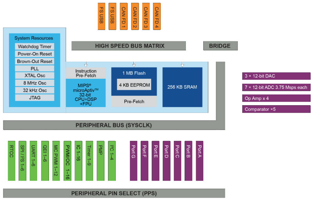 |

|
The Hardware for RobocatThe capabilities of the PIC32MK1024 permitted simplification of the printed circuit board. The new PCB consists mainly of a processor and connectors. Older versions had chips for the ADC and the DACs. The microphones and the associated amplifiers are located accross the top. There is an audio power amplifier and a voltage regulator along the bottom. The chip for the USB interface is now in the connector. The PCB was designed using Kicad. Here is the schematic. Kicad runs on any platform, is open source and completely free. Kicad is excellent and it can do anything. But there is no handholding. The PCB was manufactured in China. They did it fast and cheap and the quality was good. I have learned how to build SMD PCBs. That is another story. Robocat's Brain On A Printed Circuit Board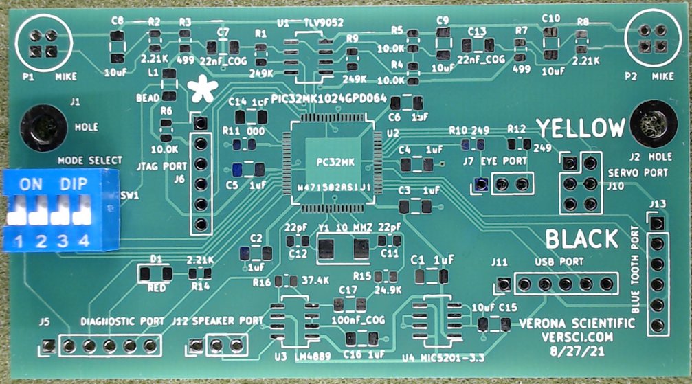
The Robocat PCB communicates with peripherals via "ports." Pin headers are used because they are convenient, reliable and cheap. Unfortunately, they are not keyed. Care must be taken. The BLUE TOOTH PORTThe latest versions of the Robocat can communicate with most Bluetooth enabled devices. It was simple and easy to connect a HC05 Bluetooth module to a UART. Each HC05 must be programmed before use with a special programmer. Robocat can program the HC05. This will be explained elsewhere. The HC05 is placed into a programmable state by pressing the Tiny Button while applying power. The HC05 does not support the new low power standard supported by Apple. And Iphones and other Apple devices do not support the old standard. It means, alas, that Robocat can't communicate with the Apple world. Android, Linux and Windows based devices will work fine. HC05 Bluetooth Module The JTAG PORTRobocat's memory must be programmed (flashed) before it can be a Robocat. This is done with a JTAG programmer. The JTAG Programmer plugs in so the stars are adjacent. The number of pins don't match, but not to worry. For convenient's sake, it is possible to extend this connector 15 cm. or so. Snap JTAG Programmer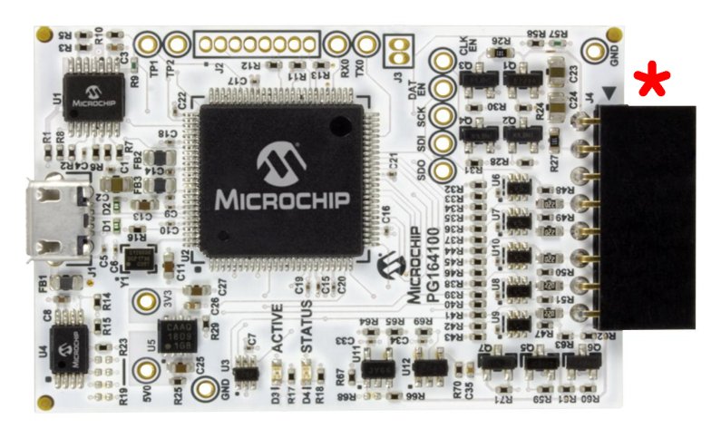 The SERVO PORTThere are two servo ports. They are the same except they rotate the servo oppositely. Certain Robocat behavior problems can be solved by switching connectors. Notice the colors of the wires on the connector of the servo when plugging it in. Servo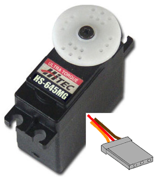
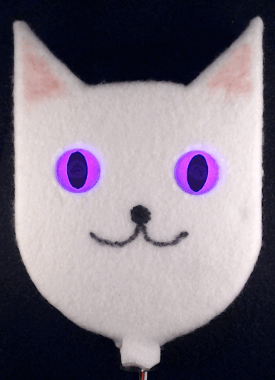
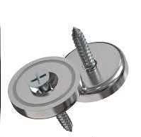
This is the servo that moves Robocat's head. A steel washer is superglued to it. A cup magnet in the base of Robocat's head engages with the washer. The cup magnet is very strong. A layer of gorilla tape prevents Robocat from hanging on to its head too strongly. The EYE PORTThis powers the leds in Robocat's eyes. It is not keyed unless you care about winks. The cup magnets are screwed to the base of Robocat's neck. Robocat's Head and Cup Magnets
The LASER PORTOK. There isn't a laser port. But the laser designator replaces Robocat's head. The laser is powered by 5 volts from the unused servo port. Observe wire colors. Robocat's Laser Designator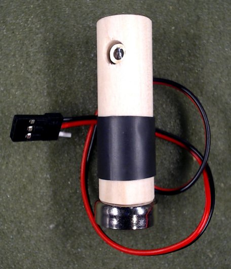
The SPEAKER PORTThis is Robocat's voice. Notice that it is 32 ohms. The audio power amplifier requires a 32 ohm speaker. Robocat's Voice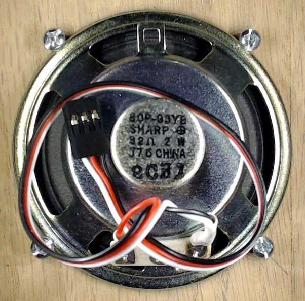 The USB PORTThe USB port has two functions. It supplys 5 volt power. And it is the serial data path. Nowadays, computers don't have serial ports. They have USB ports instead. The need for serial ports has not gone away. Specialized chips bridge the gap between USB and serial. Silicon Labs is one supplier. FTDI is another. There are several others that don't work well. And there are counterfeits. Be sure to download the .DLL driver from Silicon Labs. The original intention was to directly install the module. But it occured to me that I could extend the module with wires. That would eliminate an interconnecting cable. And Robocat would have a nondetacheable tail. Silicon Labs USB Bridge
The DIAGNOSTIC PORTThe PIC32MK1024 has two 12 bit DACs which are brought out to BNCs on the back of Robocat. A software trigger is also provided. You can use an oscilloscope to see what Robocat is responding to. This will be explained in the software description. Back End of Robocat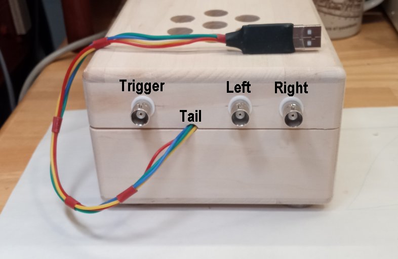
Inside RobocatThe servo is removed in this picture in order to improve visibility. The Snap programmer is suspended from a sky hook. Everything is plugged in except Robocat's head. inside Robocat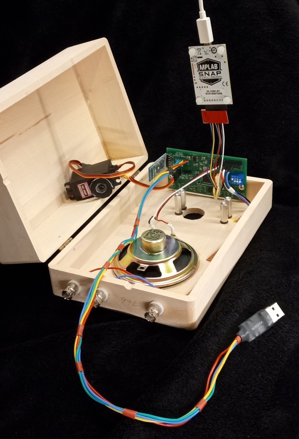
|

|